Networking and Communication
I am running out of time and this is an important assignment, this assignment will wants us to set up a communication between two or more two boards using wired or wireless communication.
I am running out of time and this is an important assignment, this assignment will wants us to set up a communication between two or more two boards using wired or wireless communication.
I have to thank Jaseel Mohammad from trivandrum 2016 batch, I refrerred his assignment this time, he has well documented all his steps and that has helped me a lot in this assignment.
I am using a BLE protocol here, BLE stands for bluetooth low energy it is runs on 20.4GHz band., Compared to Classic Bluetooth, Bluetooth Smart is intended to provide considerably reduced power consumption and cost while maintaining a similar communication range.
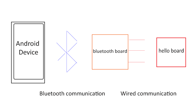
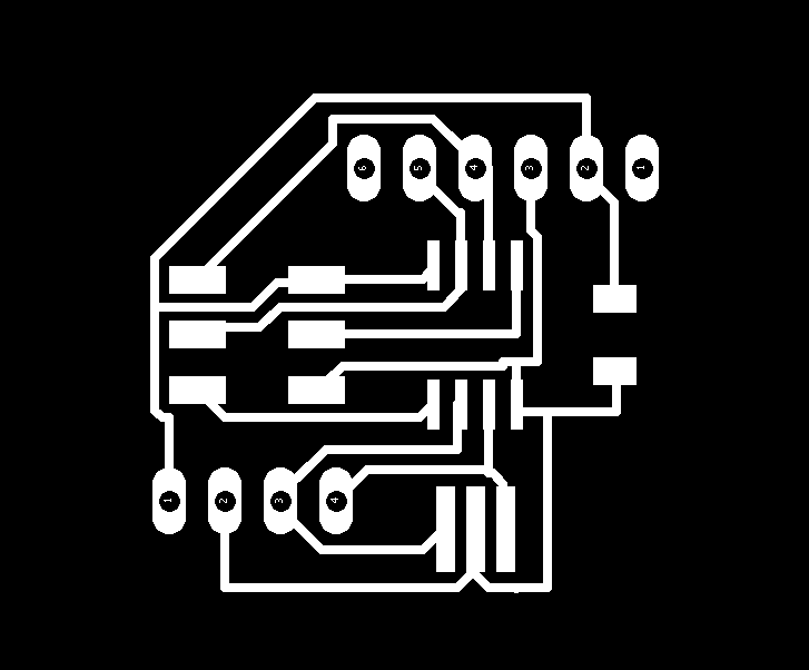
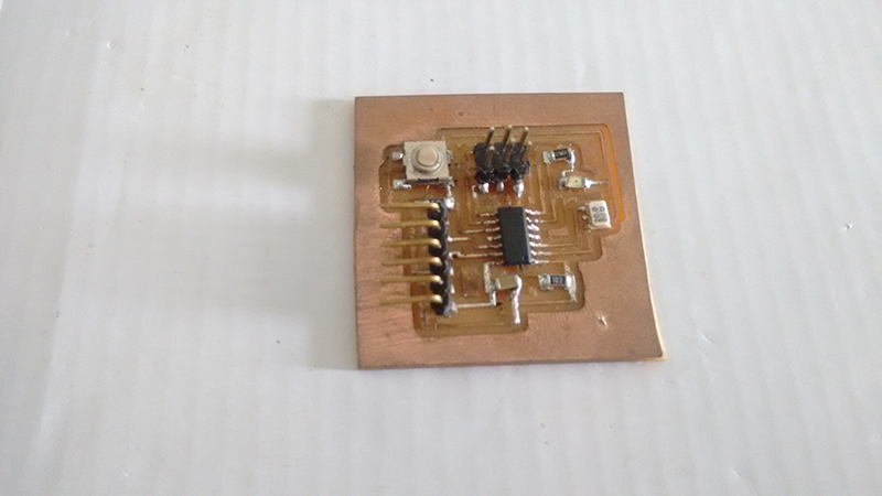
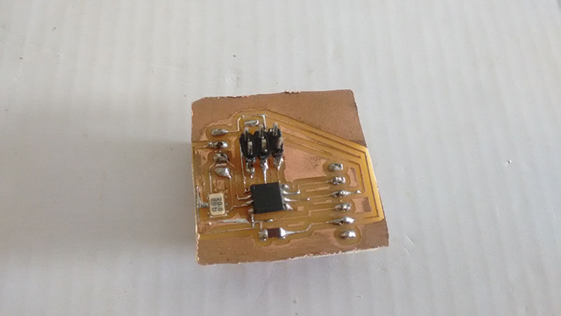
The bluetooth board has Attiny 45 as the contoller, the HC-05 has 6 terminals to it but we are only going to use 4 of them.
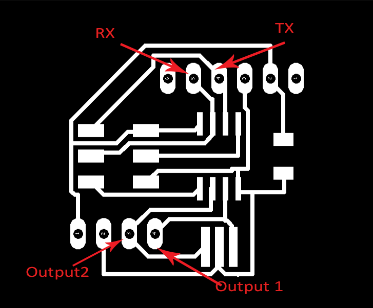
Vcc and GND connected to the corresponding pins, RX pin of the module to PB2 pin of the IC and TX pin of the module to the PB1 pin of the IC
I also took out two output pins from the IC, PB3 and PB4, these pins will be the input for the hellow board I will attaching to.
download the .SCH file from here

Here is the board with the pinouts
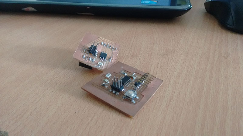
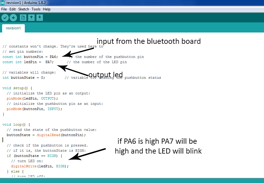
I connected the hello board to my bluetooth board using jumper wires, One thing I noticed about the hello board was that the LED was connected to the pin PA7 and PA7 did not have an input through a pin, thus I had to specify another pin as an input pin in my code, I selected PA6 as an input pin in my code.
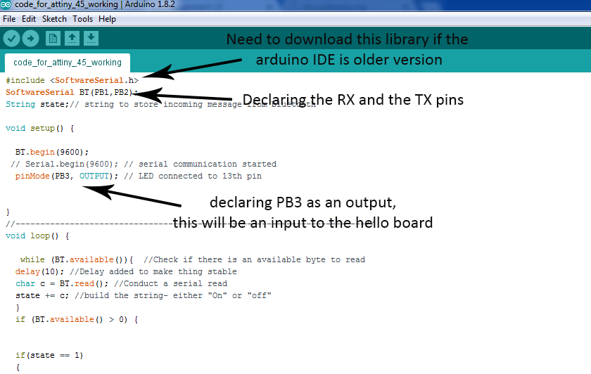
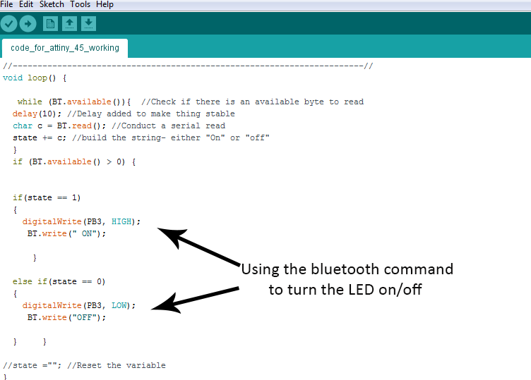
Here is my code for the bluetooth board
Here is the code for the hello board
So basically I am turning the LED on using the bluetooth as the input. The bluetooth board and the hello board are both powered by the 5V from the arduino
I am have successfully uploaded the codes in the respective ICs using arduino as ISP
I am able to detect the bluetooth device on the board through my android device
I was successful in making the boards talk to each other that means the android phone talks to my bluetooth board and my bluetooth board talks to the hello board
I am able to turn on the LED on the hello board with an android device through a bluetooth but there seems to be an error in the coding, the LED remains on forever, it does not turn off when I press the off button on the android device, there are several possibilities here
Either there is something wrong with my blueetooth code or the hello board code
OR the app I am using in this case is an app made by me for the next assignment(which I am going to discuss in the next assignment), the coding for this app might be faulty
I still figuring out the problem, I am sure that there is nothing wrong with the hardware
I was not happy with the way the bluetooth communication worked, I searched on the internet about the problem that I am facing, I got to know that the led will turn on by receiving any kind of signal, so there is a high possibility that I was not able to set up a communication between two boards.
So I decided to try another protocol, this timeRS232/RS 422/RS485
So from what I understood from Neil's lecture and some research on the internet is that a serial bus is a single line communication in which the the processors are connected to. There is a master slave relation between the processors
I am going to try the example explained by Neil in the lecture, here my computer is the master there is a bridge board which receives the Rx and the Tx line and in turn all the other processors are connected with the same Rx and Tx line.
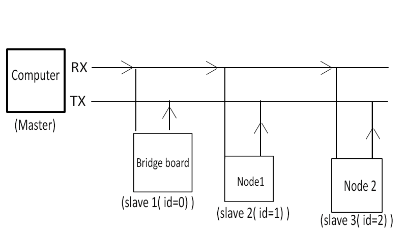
So basically what happens here is that the bridge board and the two node boards will be coded and given a unique id, in my case 0,1 and 2 respectively.
I am going to connect the computer with the bridge board with and FTDI cable, which will connect the Rx and Tx on the board to the computer, the bridge board and the nodes will be connected on a single cable using IDP headers
The pins on the board can be 0,1 or triastate, all the boards pins are triastate, their output work as an input thus when the master sends an id all the boards receive the id thus they flash and the board pin which matches the id turns into and output momentorily and flashes back.
All the leds on the boards should flash when I send any id and the board which matches the id should flash twice, this is because the board answers the master.
I am hoping this is what is going to happen
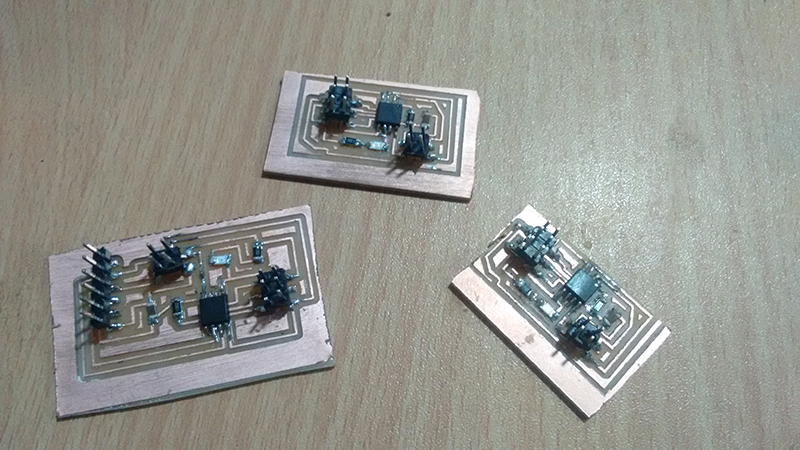
I milled and soldered my bridge and node boards and coded them with their "ids", here I am using Neil's board as reference.
Download the files bridge sch, bridge brd, node sch, node brd
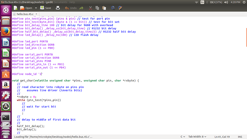
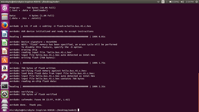
I programmed all the boards and gave them their unique ids, I used Neils make file from the schedule page and used avrdude to program the board.
I made all the connections and I tried to open term.py in windows first. It gave me this error
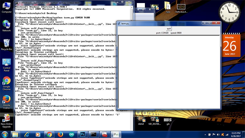
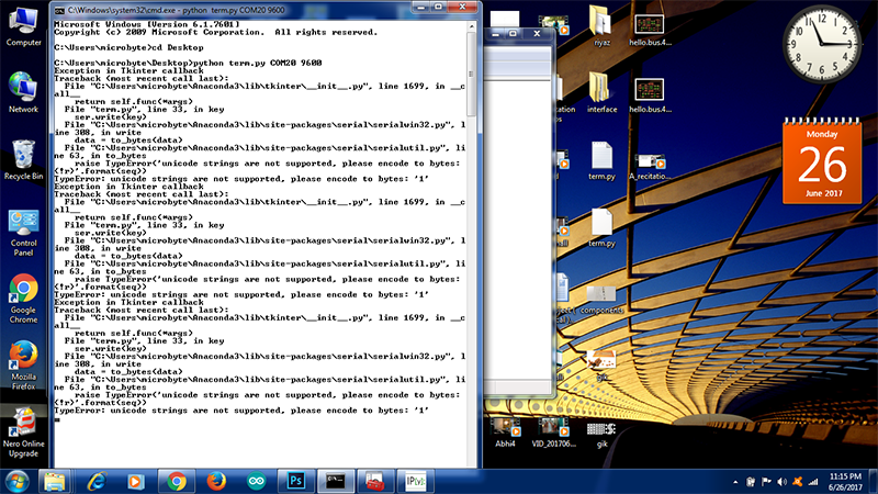
It says that unicode strings are not supported, I searched on the internet but it made me more confused, maybe I need more expertise in the coding, so I left it then and there.
I moved on to UBUNTU and used the term.py, I used this command sudo python term.py /dev/ttyUSB0 9600 here the port I am using is dev/ttyUSB0 just like COM20 in windows and the baudrate is 9600
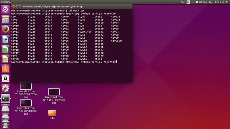
This is the result
In the video it is seen that the node1 and node0 work properly but node2 does not. There seems to be some loose in the IDP headers or the wire, I changed both but still the same.
Also it can be seen in the video that the sometimes when the node0 is pressed it does not print on the serial monitor. I dont know why this is happening.
I was able to set a communication between three boards and a computer with some gliches most probably some hardware issues
I had another option, I downloaded an app called bluetooth terminal on my android phone adn used it as my serial monitor, I gave the power to the whole system from arduino and connected the bluetooth module to the bridge board.
The bluetooth module will give the Rx and the Tx to the bridge board and thus the whole system will get the Rx and Tx
Remember to connect Rx of the bluetooth module to Tx of the board and vice versa
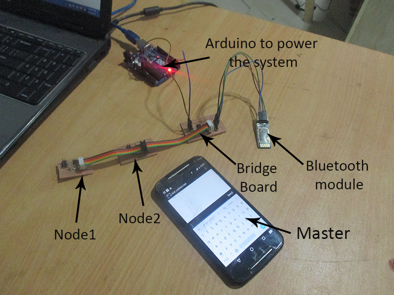
An interesting thing happened, all the LEDs on the board are flashing that means that the master is talking to the slaves and the slaves are receiving the ids, but amongst the 3 only node1 is responding when it is called
The video shows that the node1 is responding as it should be but the other two are not, there were instances when even the bridge board i.e the id 0 is also responding, but it is not consistant, I was never able to capture it in a video
This can mean a lot, there can be many reason for this, the first being that there is loose connection at the nodes, or the wire is not proper, but I changed the wire resulting in the same thing.
I checked weather the LEDs are working, they are, so no doubt there.
I reprogrammed the boards, their ids, still its the same. I am not sure, why the node1 is responding and the others are not.
I will come back to this assignment if I get time, I am very close, this seems to be a hardware error.
I am running out of time, a lot of project work is pending thus I was not able to concentrate much on this assignment.
But as Neil said the serial bus communication especially RS 422/RS485 can be used to talk between a couple of processors, it will get complicated once the number increases
I still have to figure out the python script problem, I want to be able to send and receive the signals from serial monitor
But I would like to work on this assignment, I would like to try the Serial Bus and I2C as well as the wifi and the zigbee communication
This is the most exciting assignment, there is a lot of electronics and coding involved, although I am new to all this I was getting the hold of it but unfortunately I couldnt spend much time with this
Networking and communication has a lot of application, The final project I am making is a portable geodesic dome house. There is a lot of scope of home automation where in I would apply the knowledge gained in this assignment.
It is the basis of how internet started and I would certainly love to spend some more time learning this even after FabAcademy